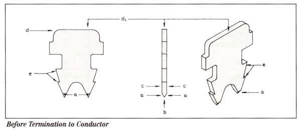
Interconnect Specialties, Inc.


It’s a good connection to have.


Located in

Southern California


Phone 714-674-5090   Fax 714-674-5088


Products


Services


Manufacturers


About


Contact


                   Home


Virginia Plastics    << back


Modular Plugs and Contacts

Modular Plugs

Male Contacts

Modular Plugs

Clear, Clear Tall Back, Special Clear

plug.jpg (7070 bytes)

Go to Catalog Page
..

Features/Benefits

  • Unique Insulation Displacement Contact 'I-PC' (interpentrating contact) technology
  • Reduced data error rates
  • Up to 10 conductor capacity
  • Provides multiple points of contact with each conductor in the plug
  • Micro-conical piercing tip contact blade
  • Precision tolerance male plugs
  • Data transmission rates above 4 Mbps
  • Minimizes standing wave reflections at contact blade/conductor interface
  • Variable strain relief accomodates wide range of cable sizes
  • Mating life of 500 cycles minimum
  • Fatigue resistant, long life springback latching arm
  • Extremely tough polycarbonate plug V-0 to V-2 rated material


Connector Technical Specifications

Electrical
Contact Resistance:  10 millohms max per contact
Intitial After Cycling:  20 millohms max.
Insulation Resistance:  1000 megohms min.
Dielectric withstanding voltage:  1000VRMS @ 60 sec. duration (adjacent contacts)
Current Rating:  3.0 amps max. per contact
Durability:  1000 min. mating cycles 

Material
Male Connector Housing:  Polycarbonate and/or polyester
Flamability Rating:  passes UL94V-0
Contact Blade:  High strength grade, Phosphor Bronze
Barrier Update:  50 micro-inch min. nickel
Plating:  (Type R1-Standard)  15 micro-inch min. AUPD gold alloy   (comparable to 30 micro-inch hard gold)  (Type R2-Optional)  50 micro-inch hard gold
Piercing Tip Area:  0.5 micro-inch minimum gold or gold alloy

Mechanical
Conductor Damage/Integrity:  6 strands not severed typical
Accuracy of Blade Targeting
:  <2 undbroken strands typical on each side of contact blade
Insertion Force:  (DT) 2lbs. max.  (SP, RC) 4lbs. max.
Plug Retention in Female:  20 lb max. load shall not disengage and maintains electrical continuity
Cable Retention in Plug:  20 lb max. load


plugcontact1.jpg (15314 bytes)
plugcontact2.jpg (20786 bytes)
plugcontact3.jpg (16436 bytes)

Piercing Tips
a-          penetrate and pass through insulation/conductor to reach final assembled position

Micro-conical Penetrating Points
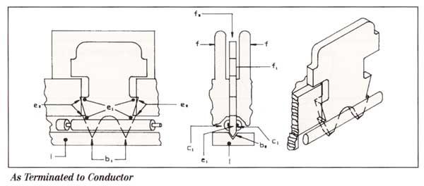
b-          extremely fine conical points of contact blade piercing tips
b1-        combs strands of conductor intop 2 groups
    -        micro size and conical shape of points greatly reduce breakage and/or damage to conductor strands during insertion
              and penetration of contact blade
b2-        forms retainer pocket in floor (i) of plug and securely seats in retainer pocket

Mating Sidewalls to Conductors of Cable
c-          flat, parallel sidewalls for mating to conductor
c1-        blade sidewalls press the two groups of strands apart to fully interpenetrate both groups conductor strands encased                by insulation are in compression against both sidewalls to provide multiple points of contact
   -         parallel mating walls (unlike angled mating walls) maintain constant contact pressure to conductor strands
   -         wraparound of conductor strands on sidewalls provides significantly improved conductor staking
   -         centering alignment reduces standing wave reflections

Top Blade Mating Area fo Mating With Female Spring Contacts
d-          curved, lead-in surface
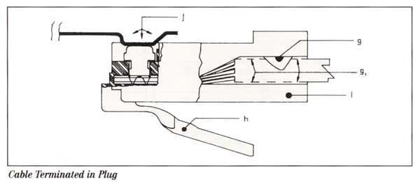
d1-        large, rectantular mating area for female spring contact (j)
    -        large, flat mating area optimizes mated reliability by providing multiple points of contact

Locking Barbs
e-          locking barbs of low contact blade to be anchored
e1-        4 anchoring points on each contact blade
e2-        unique point arrangement and wall interlock secuure contact within the plug, that cannot be dislodged under severe
             vibration and shock

Contact Alignment
f-          strong dielectric barriers between contact blades
f1-        contact is precisely vertically oriented, centered between dielectric barriers
f2-        provides optimum alignment with spring contact of female connector
   -        prevents drag or entrapment of female spring contact by eliminating contact blade slant

Cable and Plug Positive Retention
g-          integral, molded cable locking bar (strain relief)
g1-        cable capture area in plug housing
h-          integral, molded latching arm
  -          excellent memory gives dependable springback, providing positive retention within female connector
  -          high fatigue resistance design prevents latching arm sag caused by field use

Connector GuideHome Page

For more information, please call us at (714) 674-5090 or FAX (714) 674-5088.
Interconnect Specialties Inc.
590 West Central Avenue
Unit H
Brea, CA  92821
inspinc@aol.com